
All prices without VAT.
Biogas multi-stage compression plant development

The aim of the project is to carry out research in the biogas compression cycle with the aim of achieving the required biogas parameters (pressure, temperature) at the reactor inlet while controlling and managing the process at each stage of compression.
Aim: To develop a self-regulating automatic biogas compression system to operate a biogas reactor.
Main activities in the experimental development
- Modelling of the thermal processes in the compression process and design of an experimental two-stage biogas compression plant
- Fabrication of the experimental two-stage compression plant
- Experimental studies of the compression process and verification of calculations using atmospheric air instead of biogas
- adjustment of the design and control of the compressor station on the basis of experimental data
- Testing and development of the compressor station under real conditions in a biogas plant
Result: self-rotating automatic biogas compression system for biogas reactor operation
31.12.2025.
Several blocks have been prepared for the manufacture of a two-stage compression station.
Controls;
Compression unit base frame;
Electric motor mounting mechanisms, belt tensioning;
Cooling unit – chiller.
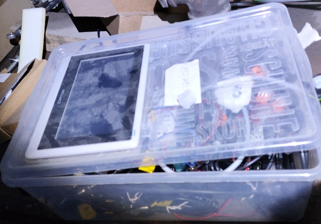
The control unit prototype was manufactured by assembling a PLC – a programmable logic controller with several temperature and pressure inputs.
An HMI (human-machine interface) was programmed to view data and control the prototype, displaying information from temperature and pressure sensors.
The control unit will record data in an electronic file. The data will be analyzed as a set of information in order to develop the most optimal operating mode.
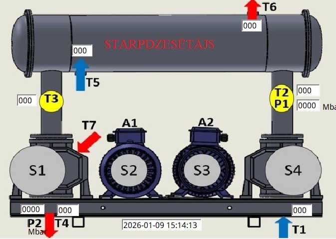
Six temperatures are displayed on the control unit screen. The inlet temperature T1 is required to calculate the temperature increase. Temperature T2 is after the first compression stage. When operating at one stage, the outlet temperature T2 can usually reach up to +80°C, which is too high to enter the second compression stage. Therefore, it needs to be reduced. The temperature after cooling heat exchanger T3 will provide information about air cooling. It will definitely need to be lowered to +40°C so that the second compression stage does not overheat. The main temperature load is on the bearings, which themselves can reach an operating temperature of +120°C when working under load. The correlation between the outlet pressure P2 and the outlet temperature T4 will provide information about the efficiency of the cooling heat exchanger. The heat exchanger receives temperature T5 from the cooler, the heat carrier is heated by the passing gas and returns to the cooler at outlet temperature T6. By changing the temperature T5 of the cooling fluid supplied, it is possible to achieve more efficient cooling.
The energy consumption of the prototype will be calculated using the consumed currents A1 and A2. Each compression stage is driven by a separate electric motor. A variable frequency unit will also be added when improving the compression stage prototype. This will change the motor speed so that data can be collected at different loads.
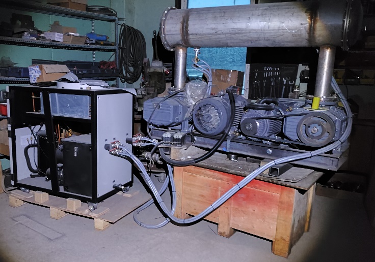
The compression station is assembled and ready for experiments.
A prototype of the two-stage
compression station is manufactured and connected to sensors to be able to read
operating indicators.
The control unit converts sensor
signals into a human-readable format – pressure, temperature, engine speed.
|
|

Fig. 2
Control unit screen
The control unit screen displays
six temperatures. The inlet temperature T1 (Fig. 2) is necessary to calculate
the temperature rise. The temperature T2 (Fig. 2) is after the first degree of
compression. When operating on one stage, the output temperature T2 can usually
reach as high as +80°C, which is too high to enter a second compression stage.
Therefore, it is necessary to reduce it. The temperature after cooling, the
heat exchanger T3 will provide information about air cooling. It definitely
needs to be lowered to +40°C to prevent the second compression level from
overheating. The main temperature load is on the bearings, which, when
operating under load, can reach up to +12°C. Correlation of output pressure P2
(Fig. 2) with the outlet temperature T4 will provide information about the
efficiency of the cooling heat exchanger. The heat exchanger receives
temperature T5 from the cooler (Fig. 2), heats the heat carrier with the
passing gas, and returns the output temperature T6 to the cooler. By changing
the temperature of the supplied coolant T5, more efficient cooling can be
achieved.
The planned temperature reductions
were divided into two phases.
The first method uses cooling water
taken from the water system.
In the second phase, a heat pump –
a chiller – is connected. The coolant is in a closed system where it is heated
by the working gas and cooled by a chiller-type – refrigerator-type cooler that
transfers heat through the radiator into the atmosphere.
